Fault Pre-locating with the TEC-X35
[ Step 1 ] [ Step 2 ] [ Step 3 ] [ Step 4 ]
Introduction
Before attempting to use the X35 to pre-locate feeder faults, it is important to fully understand the operation of the X35. Once the X35’s basic operation is understood, the operator will find the X35 to be an indispensable asset in the fault localization procedure. Field measurements have shown the X35 is very successful in pre-locating network feeder faults on properly bonded feeders. However, there are certain conditions which may make the X35 ineffective. If your network system has good feeder bonding and you are having difficulty locating faults with the X35, please re-read the "Fault Pre-locating Tips and Frequently Asked Questions" section of this manual.
The X35 is used to take a series of readings of Thumper or Thyratron Test Set signals above the faulted feeder, beginning near the Test Set location and working out along the feeder toward the fault. Where a feeder branches, the faulted branch generally has the largest reading. This tracing procedure continues until the reading drops off significantly indicating that the fault has been passed.
The following detailed steps assume that either Thumper, Thyratron, or Hipot pulses are being applied to the feeder.
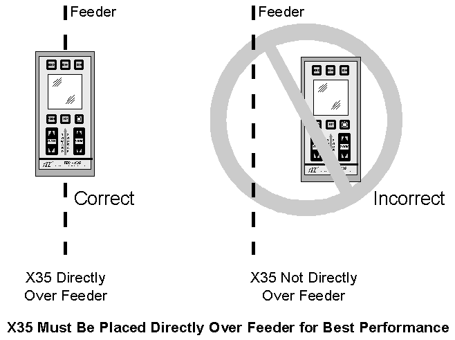
Step 1: Aligning the X35 Over the Feeder
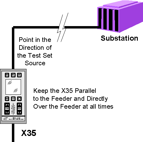
For proper operation, it is essential to align the X35 unit with the feeder. The red arrow with the surrounding words "Toward Source" on the front of the X35 must be aligned "parallel" to the feeder, directly over the feeder, and point in the direction of the Test Set (see figure below).
The X35 must always point parallel to the feeder and in the direction of the Test Set source (see figure below).
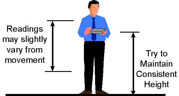
Since X35 readings will vary with height, it is also important to hold the meter at a constant distance above ground. A general rule would be to hold the X35 at waist level. To determine the location of the below ground feeder, the operator should take multiple readings, moving across the perceived path of the feeder, until a maximum signal is detected.
If a Thumper or Thyratron signal is weak due to excessive depth, a low output Test Set, or poor conditioning of the feeder, the X35 may be placed on the ground. By placing the X35 on the ground, the sensitivity is increased by approximately a factor of 4 when compared to holding waist high, which will help detect weaker Test Set signals.
Do not place or hold the X35 on top of manholes or large metal plates as these materials may deflect the magnetic field generated by the Test Set.
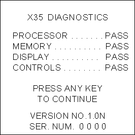
Turn on the X35 unit. After the diagnostics complete, the X35 is in the standby condition waiting for the operator to press a button ("press a key"). Any button, except the power "ON" or "OFF" button, may be pressed. The purpose of this requirement is to enable the X35 to automatically shut off in case the unit is inadvertently turned on. If no key is pressed, the X35 will shut off in 1 minute to conserve battery power.
Once a button is pressed, the X35 will default to Thumper or Hipot processing. If Thyratron processing is required, press the MODE button once to configure the X35 for Thyratron Test Set signals. The processing mode, Thumper or Thyratron, must match the setting of the Test Set. The processing mode is controlled by the "MODE" button, which toggles between the Thumper and Thyratron modes when pressed. When the operator changes the processing mode, the display X35 will inform the operator that it is configuring itself for the selected mode. Once configured (about 2 seconds), the display will begin showing the sensor data. When changing modes, all data from the previous mode will be lost.
In addition, due to internal circuit switching, a small amount of high level noise peaks may be displayed on the screen for the first second after a mode change. This is normal and should not be mistaken for Test Set pulses.
Step 3: Selecting the Correct Gain Setting
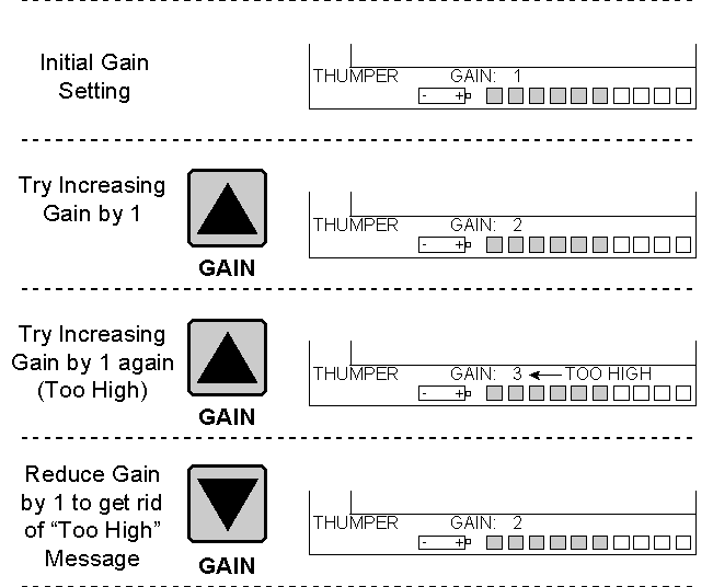
There is no utility standard regarding the feeder depth or Test Set output level. To support this uncertainty, a Gain selection switch is included to optimize the performance of the X35. FOR BEST RESULTS, THE GAIN SETTING SHOULD BE SET AS HIGH AS POSSIBLE WITHOUT THE "TOO HIGH" INDICATOR TURNING ON. Gain boosts the sensor signal level to put it in the best range for processing. Because the sensor signal varies from place to place along the feeder, the gain should be set EVERY TIME before taking a reading at a new location. If the gain is too large or too. small, the X35 readings can be degraded.
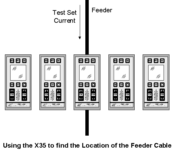
While setting the gain, the operator should begin to see Thumper or Thyraton Test Set pulses assuming the X35 is positioned over the faulted feeder. If not, try Zooming In or Out with the Zoom keys. To assure the X35 is correctly positioned over the feeder, try moving it from side to side and measure the level of the Test Set pulse. The highest reading will be when the X35 is centered directly over the feeder. This concept can also be used to find the location of a feeder if it is not known.
Before setting the gain, make sure the X35 is still positioned waist high directly over the feeder cable with the red "TOWARD SOURCE" arrow "parallel" to the feeder and pointed in the direction of the Test Set. To set the gain, add gain by repeatedly pressing the GAIN up arrow button until the "Too High" message is displayed next to the gain level (see figure below).
 If the
"TOO HIGH" message is displayed, press the Gain DOWN key once to clear it.
If the
"TOO HIGH" message is displayed, press the Gain DOWN key once to clear it.
IMPORTANT: THE "TOO HIGH" MESSAGE IS GENERALLY ONLY DISPLAYED WHEN THE X35 IS DETECTING THE THUMPER OR THYRATRON PULSE OR IN ELECTRICALLY NOISY ENVIRONMENTS. IT IS THEREFORE IMPORTANT TO WAIT FOR 1 OR 2 TEST SET PULSES TO OCCUR BEFORE DETERMINING IF THE "TOO HIGH" MESSAGE FLASHED ON THE SCREEN. THE "TOO HIGH" MESSAGE WILL GENERALLY ONLY FLASH FOR ABOUT 1-2 SECONDS ON THE SCREEN TO INDICATE THAT THE GAIN IS SET TOO HIGH. THE OPERATOR MUST BE CAREFUL TO WATCH THE DISPLAY TO SEE IF THE MESSAGE IS DISPLAYED.
There are 3 gain settings. Gain 1 is the smallest and Gain 3 is the largest. The gain setting in use is displayed at the bottom of the display next to the word "GAIN". When the gain is changed (up or down arrow pressed), a small amount of data (about 1 second) will be lost. In some instances, some transients may be seen on the display at the time gain settings are changed. This is normal and the switching noise should not be mistaken for Test Set signals.
Changing the gain within the allowed range does not change the size of the displayed signal. When the gain is scaled up or down, little or no change in the signal amplitude should occur. However, operating the X35 when the "Too High" message is displayed may clip the viewed Test Set signal providing a false signal level reading.
Step 4: Read and Note the Peak DC High Voltage Test Set Signal Level
Once the X35 is positioned correctly over the feeder and the gain set correctly, Test Set signals should be present on the X35 display (assuming the fault has not been passed). The display can be Zoomed "In" or "Out" for ease in reading. Pressing the Zoom "In" button (up arrow) will double the size of the display information. Pressing the Zoom "Out" button (down arrow) will halve the size of the display information. The actual signal level will not change. It will simply be enlarged or reduced for easier reading. It is important not to Zoom in "too far" so that the Test Set signal level information is too large for the screen. If this is done, the signal level is not accurately being measured. A Test Set signal with a level of "6" will be clipped at "4" if you are Zoomed in to a level with a maximum scale of 4, providing an inaccurate measurement. Always Zoom in enough such that the Test Set signal does not exceed the top of the scale.
Typical Thumper pulses (below) appear in the display as regularly spaced narrow peaks separated by 6-7 seconds (depending on the adjustment of the Test Set).
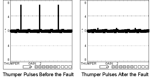 Prior to
the fault, pulses should appear high in amplitude. Once the fault has been passed, or if
you proceed down an "unfaulted" leg, the pulses will drop in amplitude to almost
zero or become negative.
Prior to
the fault, pulses should appear high in amplitude. Once the fault has been passed, or if
you proceed down an "unfaulted" leg, the pulses will drop in amplitude to almost
zero or become negative.
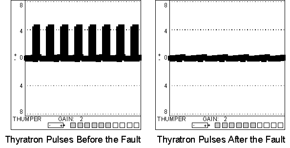 When
operating a Test Set in the Thyratron mode, pulses will appear more broader (0.5 to 1.5
seconds wide) than the Thumper pulses and are usually spaced closer together (3 to 5
seconds apart). Thyratron processing is unipolar and does not show the direction the Test
Set signal emanates from. Therefore, all pulses will be presented as "positive".
Prior to the fault, Test Set pulses should be prominent, while after the fault, Thyratron
pulses will be almost non-existent.
When
operating a Test Set in the Thyratron mode, pulses will appear more broader (0.5 to 1.5
seconds wide) than the Thumper pulses and are usually spaced closer together (3 to 5
seconds apart). Thyratron processing is unipolar and does not show the direction the Test
Set signal emanates from. Therefore, all pulses will be presented as "positive".
Prior to the fault, Test Set pulses should be prominent, while after the fault, Thyratron
pulses will be almost non-existent.
Note: The actual timing of the Thumper and Thyratron Test Set pulses are adjusted by settings on the DC high voltage test set.
When taking any reading, it is important to assure the X35 is correctly positioned over the feeder. Re-centering the X35 over the faulted feeder by moving it from side to side (keeping it parallel to the feeder and pointed toward the source) across the feeder to obtain the highest reading is suggested. When satisfied with the alignment, read and note the average height of the signal peaks. (Ignore any peaks caused by background fields or transients.)
At a feeder "Tee", the X35 can be used to identify the faulted leg by taking readings over both legs leaving the "Tee", after they separate from each other (see figure next page). Do not take readings too close to the "Tee" itself. It is a good rule of thumb to position yourself at least 20 feet from the actual "Tee", or even better, go to the next manhole of each leg to take a reading. This is to prevent the two magnetic fields generated by the separating feeders from conflicting with each other. The peak signal is normally largest on the faulted leg. Also, with a Thumper or Hipot, pulses on the unfaulted leg will often be negative.
If a measurement is made too close to a "Tee" or similar separation in cables, pulses displayed on the X35 may go both positive and negative. If this situation occurs and the readings at the "Tee" are inconclusive, taking readings on each leg 20 to 30 yards further away from the "Tee" may help.
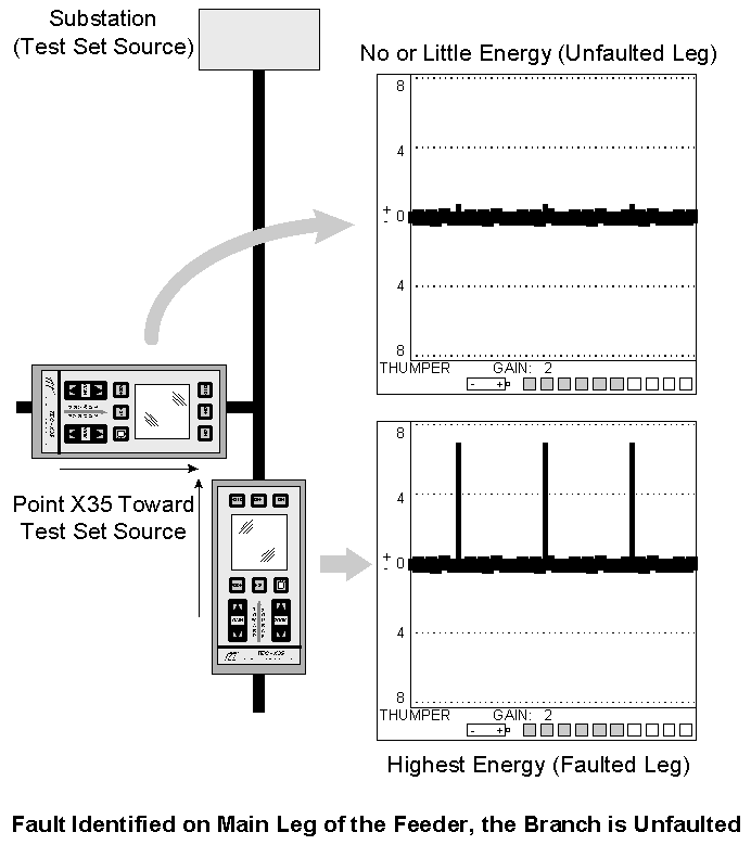 If when
traveling along the feeder, the peak signal drops greatly from previous readings or cannot
even be found, the fault has been passed. The fact that the fault has been passed should
be confirmed by taking an additional reading one manhole beyond the point where the peak
signal drops sharply. In the above example, the branch off the main leg is unfaulted and
the operator should continue down the main leg (which is the highest reading). The
operator may continue traveling the route of the feeder or go to the next major
"Tee" and take another measurement. If there is no signal going into the
"Tee", the operator has passed the fault. If there is still strong energy going
into the "Tee", another set of "Tee" measurements should be made
similar to the above example to determine which direction to follow.
If when
traveling along the feeder, the peak signal drops greatly from previous readings or cannot
even be found, the fault has been passed. The fact that the fault has been passed should
be confirmed by taking an additional reading one manhole beyond the point where the peak
signal drops sharply. In the above example, the branch off the main leg is unfaulted and
the operator should continue down the main leg (which is the highest reading). The
operator may continue traveling the route of the feeder or go to the next major
"Tee" and take another measurement. If there is no signal going into the
"Tee", the operator has passed the fault. If there is still strong energy going
into the "Tee", another set of "Tee" measurements should be made
similar to the above example to determine which direction to follow.
NOTE: Due to changes in feeder depth and interference from stray magnetic fields reaching the X35, the readings will vary in amplitude along the length of the feeder. For example, if a reading with a magnitude of 10 was made at one location, and the reading dropped to 4 at the next location, the fault probably hasn’t been passed yet. It’s more likely that the X35 will read below 1 when the fault has been passed. If the fault location is still unclear after the meter reading drops, backtrack until the reading jumps back up.
The signal level drop that shows the fault has been passed occurs at the first good bonds nearest the fault. This can cause some confusion if the fault is in a manhole on an improperly bonded feeder, as sheath current will flow to the nearest bonds, some of which could be beyond the fault. The X35 cannot distinguish phase current from sheath current which is why it cannot be used to pin-point feeder faults.
